hra fb twitter
sheffield
header

Main Cylinders

First First Previous Previous uparrow Back to Index Next Next Last Last
143 records found. Page 3 of 15 displayed.

For most of the photos on this page, you can click the image for a larger picture.

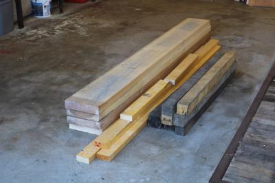
Highslide JS This is how the timber arrives from the timber yard. A bit of work is required before we can use it in our pattern.
Each section of the motion piston cylinder pattern is laminated from 2 inch thick boards of Quebec Yellow Pine, which is a soft, straight grained and even textured timber used widely for pattern stock, sat on a 24 mm Birch WBP (Water and Boil Proof) ply moulding board.
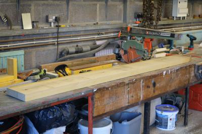
Highslide JS The first process is to cut the timber up into the right lengths.
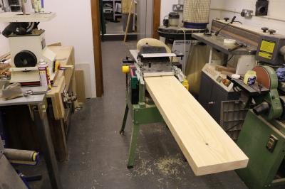
Highslide JS Then its onto the planer/thicknesser where the boards are planed down to exactly the right thickness and given a fine finish.
Highslide JS Tony has to think about how to make the pattern and how to get the pattern out of the mould. He's also got a problem in that the cylinder is too wide for his lathe. So in addition to the the 4 horizontal layers, he's also got to divide the cylinder in half vertically so that the width will fit in the lathe and he's able to turn it. So he's got to produce 2 sets of 2 semi circles. He's calling them quarters but that just ends up confusing me as I look for something with a 90 degree angle!

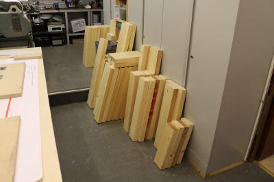
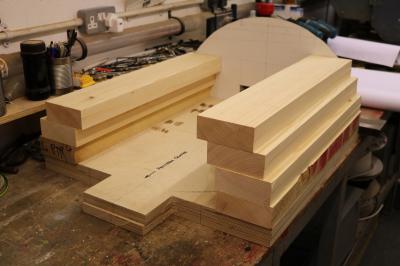
To keep the weight down, the section is partially hollow. Here you can see the blocks of timber cut to the right length.
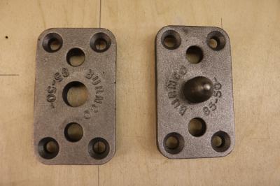
Highslide JS These are pegs and sockets that are used to ensure that the 2 halves of the pattern (i.e. the 2 semi circles) are always positively located together. Model railway builders use something similar to locate 2 baseboards and retain track alignment.
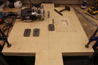
Highslide JS In order to make sure that the 2 plywood moulding boards are accurately aligned, it's important that the pegs and sockets are accurately positioned. Tony has made a router jig and temporarily screwed it to the moulding board. He can then use the router to cut the recess for the pegs and sockets. Note the words "Inside" drawn on the board. It's all too easy to mix up parts!
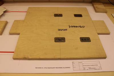
Highslide JS Keith creates drawings that are one eightieth bigger than the required final size to allow for shrinkage in the casting mould as the molten metal cools. Tony creates a plywood layout board from the drawing. Each half section of the motion cylinder pattern will be made in 2 semicircular patterns. They will be located together using the metal pegs that you can see on the board.
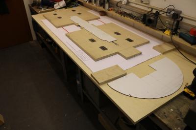
Highslide JS We're now ready to start building up the pattern from blocks of wood. The semi circle nearest the camera is a template which reflects the finished size after the cylinder is turned. The boards need to be bigger than this as you will see in the next photo.
Highslide JS Here's the first trial run. The circular template is used to ensure that sufficient wood is outside the circle so that the turned pattern will be truly circular while retaining as much as possible within the circle for strength.
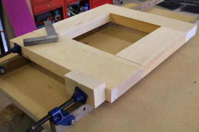
Highslide JS The first layer in the pattern is critical as this is the foundation for all of the layers above it. Absolute squareness is a must.
First First Previous Previous uparrow Back to Index Next Next Last Last
143 records found. Page 3 of 15 displayed.