Exhaust Steam Manifold
For most of the photos on this page, you can click the image for a larger picture.
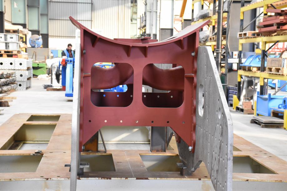
This page is the story of the making of the exhaust steam manifold. You don't see this component mentioned in locomotive books. The manifold is used in outside cylinder locomotives and performs the same function as the exhaust manifold in a car in that it provides a passage for the exhaust gases from the cylinders. Like a modern car (with turbocharger), the exhaust gases are used to improve the efficiency of the engine.
In the photographs you can see the 2 main frame plates (in grey) standing vertically. The red block between the frames is the fabricated smokebox saddle/frame stretcher and cast exhaust steam manifold. The manifold is cast first and then it is welded into the smokebox saddle/frame stretcher.
Normally the manifold would be cast in the normal way, i.e. make a wooden male pattern, pack foundry sand around it to make a female mould and finally pour in molten metal to produce the component. See the cylinder page for a fuller explanation.
A wooden pattern had been built but this had suffered from years in storage so, in late 2015, a decision was taken to explore alternative methods of producing a new one. A new technology has emerged, that of sand printing. Sand printing is similar to 3D printing in that a specialised 'printer' prints layer of sand and resin and produces the female mould directly from the CAD model.This type of casting is cheaper for one-off parts, like the exhaust steam manifold. For parts like the outside cylinder, where the pattern can be re-used, conventional wooden patterns are cheaper. We believe that this is the first time any large major component has been produced, using this method, in the history of British Steam Locomotive building.
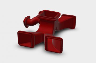 |
This is the CAD model of the exhaust steam manifold. The 2 exhaust ports from one of the outside cylinder are in front. The 4 exhaust pipes combine together for the top outlet which is directly under the blastpipe. The exhaust steam goes up through the blast pipe to the chimney. Importantly, it creates a vacuum in the smokebox which draws the fire down the fire tubes from the firebox. The harder the engine is worked, the more exhaust steam is produced and the stronger the draught on the fire. The pipe to the left provides exhaust steam for the exhaust steam injector.
The gases must flow cleanly through the manifold. The holes through the frame are cut at the same angles as the manifold gas ways so that no sharp edges are present which could cause turbulence. |
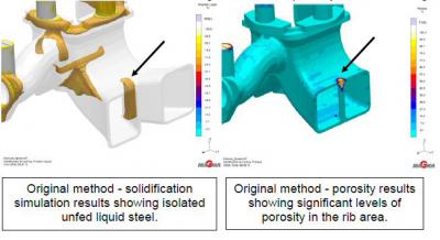 |
Computers have made significant impacts into all areas of engineering and casting is no exception. Computer modelling was used to analyse how the metal would behave during the casting process.With the need to produce a good casting right first time; Maxima Engineering (UK and ROI agents for MAGMASOFT) were contacted to assist with the development of a suitable casting method. The original foundry method was simulated using MAGMASOFT. This simulation indicated a large area of isolated liquid steel during solidification shown on the left hand image. This resulted is a significant risk of porosity shown on the right hand image |
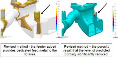 |
Following a review of the design it was decided to add a small pad above the rib area effected, to allow a molten metal feeder to be placed and thus allow for direct feeding ( left). This pad allowed directional solidification to the feeder and significantly reduced the predicted porosity risk (right). The area of porosity has now moved to a metal feeder which will be removed during fettling. |
 |
The mould was printed and delivered to Boro Foundry in Lye, West Midlands.
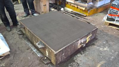
The starting point is a casting box packed with foundry sand to give a flat surface. You can see the part of the mould in its wrapping in the top right of the photo. |
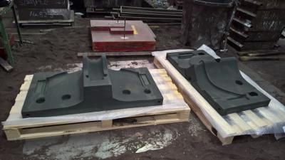 |
These 2 sections are the first 2 parts of the sand printed mould and are the bottom of the exhaust steam manifold. The exhaust steam services take off can be seen on the left.
It can be seen that the mould has a very clean surface. |
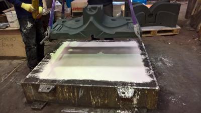 |
The surface of the casting box is treated with a sizing compound. The first section of the mould is lowered onto the casting box.
In the top right of the photo can be seen the central core of the pattern. This will be used to produce the steam passages in the final part. |
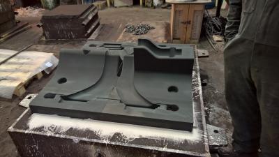 |
The second section of the mould is now added. The bottom section is now complete |
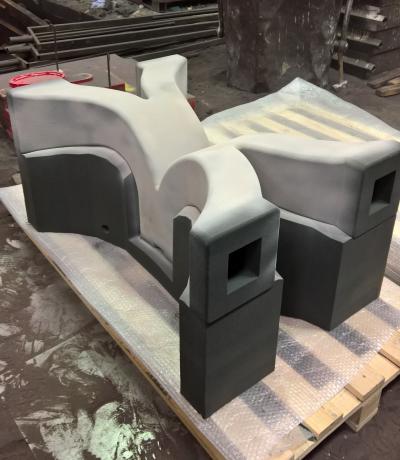 |
The central core of the mould is also sand printed. This will be used to ensure that the steam passages are formed in the manifold. |
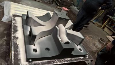 |
The central core is added to the mould. You can see how the ends of the core are positively located in recesses in the bottom moulds. You can see the gap between the central core and the bottom mould where the metal will flow to form the casting. |
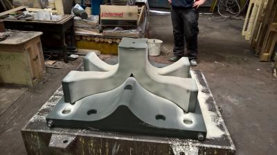 |
Here's a view from the other side |


