hra fb twitter
sheffield
header
Rail200

Frame Assembly Phase 1

First First Previous Previous uparrow Back to Index Next Next Last Last
82 records found. Page 4 of 9 displayed.

For most of the photos on this page, you can click the image for a larger picture.

Highslide JS September 2020

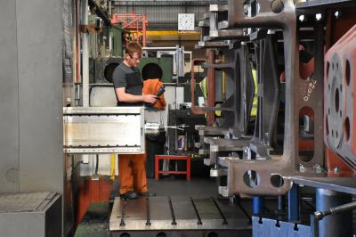
A dial gauge is used calibrate the cutting head.
Highslide JS September 2020

The cutter head starting work.
Highslide JS October 2020

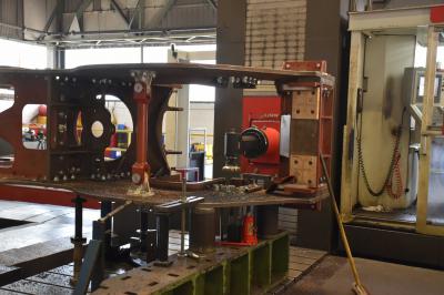
The job nearing completion. You can see the machined hornguide face.
Highslide JS November 2020

With the frames back in the assembly shop, it was time to start looking at assembling the buffer beam. This area differs from the rest of the frames as British Railways specified hot riveting in this area as opposed to cold riveting else where. The buffer beam is stiffened by internal (i.e between the frames) and outside triangular gussets. These gussets need to be built up in place. First job is to fit the flange plates.
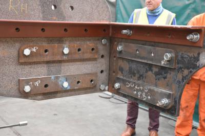
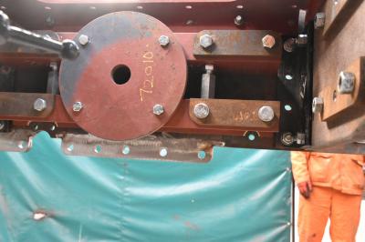
Highslide JS This is the assembly behind the buffer beam. First 2 U channels are bolted to the buffer beam - ultimately, the bolts will be replaced by rivets. The gussets flange plates are bolted to the channels. In the centre is a large disk. The drawbar goes through the hole in the centre and a drawbar spring bears on the plate.
Highslide JS November 2020

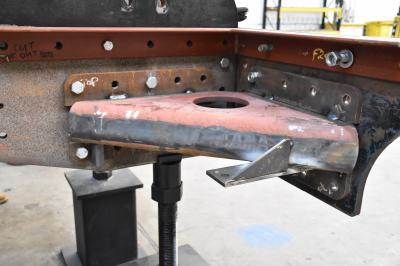
One of the outside gussets with all components tack welded into place. The plates in the foreground support the front steps. The assembly can now be removed from the frame for welding to be completed.
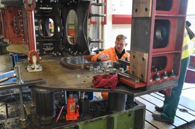
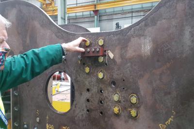
Highslide JS Mike offers up one of the grease nipple mounting blocks which lubricate the hornguide faces. As we are using fitted bolts, we will need to manufacture some "stand offs" so that the pipework will not foul the bolt head.
Highslide JS January 2021

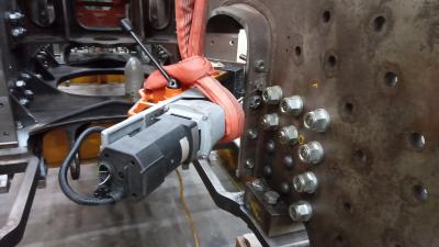
A job that could not be completed on the Juaristi machining station. It was necessary to drill and tap the lubrication holes for the hornguides as these are on the inside of the frames; unreachable by the cutting head. A jig has been manufactured for the magnetic drill. First job is to drill out the lubrication hole through to the hornguide face.
Highslide JS May 2021

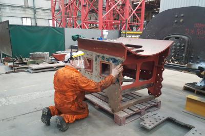
Our next major job was to fit the smokebox saddle to the frames; the intention is to ensure that we have a steam tight joint. The smokebox saddle is extracted and Dave Reynolds from the East Lancashire Railway applies a coating of engineers blue.
Highslide JS May 2021

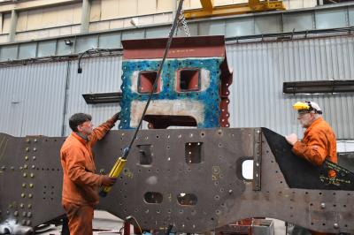
The smokebox saddle stretcher is then lowered into position. Anthony Pilkington from CTL Seal on the crane controls while Dave checks that the stretcher is going in the correct place.Once the stretcher was in place, temporary bolts were fitted and tightened up with an air gun. Where the stretcher makes contact with the frame plate, the engineers blue will be transferred, showing the high spots. After all of the bolts were tightened, they had to be removed again and the smokebox saddle lifted out. Note that the frame plates were shot blasted before any assembly work started to remove mill scale.
First First Previous Previous uparrow Back to Index Next Next Last Last
82 records found. Page 4 of 9 displayed.