For most of the photos on this page, you can click the image for a larger picture.
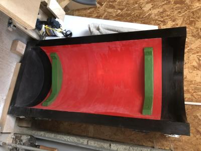 |
For the Main Cylinder Core box, to prevent having to make a top and bottom section, we have made one half that can be modified to do the work of both top and bottom by the addition of 'loose pieces' that can be removed for one half of the core and added for the other. In this case, a loose piece added makes a hole or depression in the core and leaving it out leaves the core clear. The depressions in the core are used to locate the steam transfer ports cores. The photo shows the completed core th box with the 2 loose pieces (brown) in place to form part of the transfer ports between the main and valve cylinders. |
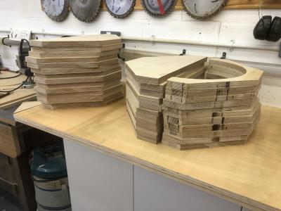 |
Tony is working on the valve cylinder core box at home. Tony says "The core including the prints is 68 ins (1.72m) long, add in a few inches for the end taper bits, so I’ve made the box 71 inches (1.8 m) long. There are currently 11 finished sections, 3 waiting fettling with the sander and 28 waiting routing , adding up to 42 sections". Tony reckons he will need to make 70 blanks. Each blank weighs 1.87 kg, we will need the box itself and some print sections on the end - the whole core box is going to be heavy when its finished. |
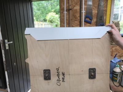 |
In order to join the 2 "quarters" of the main cylinder pattern, Tony needs to make sure that they are tightly joined together. To do this, Ruth and Tony have made up a template to ensure the join profile is correct. Here is the template profile. |
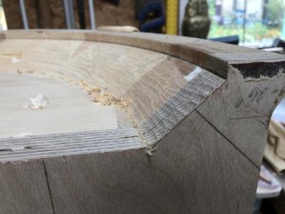 |
The excess stock from the turning process is removed. |
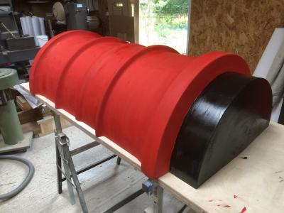 |
The top half of the pattern is now joined and has had an application of a first coat of foundry Pattern Coat red and black. Tony says "To refresh memories for our chosen colour scheme, red denotes the parts of the mould which come into contact with the molten iron, black for the core prints which form the depressions in the moulding sand which are not part of the finished casting, which locate the core sections and finally, green (not brown) for the loose pieces which are removed or added to modify the pattern or core. This first coat of pattern paint will highlight the areas which require and extra sanding and filling. Any heavy wooden softwood pattern picks up dents and scratches, so this was the first fill so to speak." |
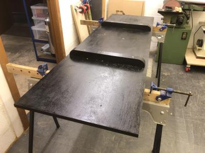 |
Over at Tony's workshop, Tony has been working on the core box for the valve cylinder. This is the base, upside down, with the feet added. |
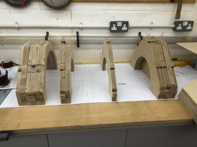 |
This shows how the core box sections are being checked against the drawing. You can see the different profiles required. |
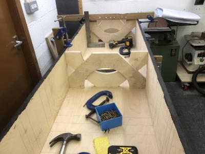 |
Tony is now building the box that will hold all of the sections for the valve cylinder core. As the box develops we will start to see the internal shape of the valve cylinder. This is the box under construction being carefully checked for squareness. Tony says "accuracy to the thickness of a HB pencil"! The 4 formers in the box are just to help keep everything square and parallel. |
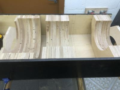 |
Sections now can be added to the box to make the correct internal profile. |
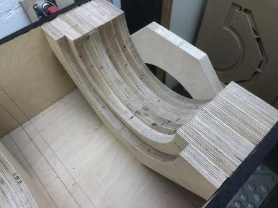 |
Tony has now changed the template on his router table and is producing the sections for blanks for th exhaust steam gallery (at either ends of the valve cylinder) and the oil gallery. The oil gallery is part of the original design where atomised oil is introduced into the gallery and then fed into the cylinder through the liner via a series of holes circumferentially around the liner. For HENGIST atomised oil will be replaced by oil being injected directly into the valve cylinder. A boss in the casting will bypass the gallery. We will retain the gallery in case the pattern should be required by 70000 or 70013. |


