


Main Cylinders
 |
First |  |
Previous |  |
Back to Index | ||||
| 240 records found. Page 24 of 24 displayed. | |||||||||
For most of the photos on this page, you can click the image for a larger picture.
 |
And this job is complete |
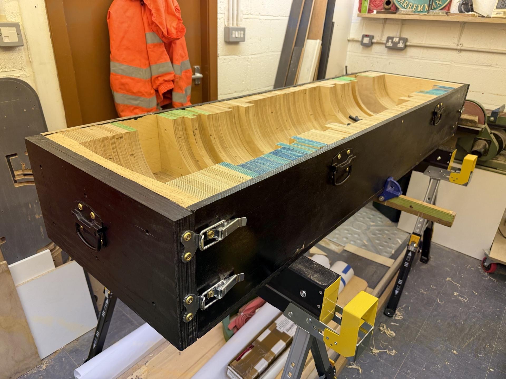 |
The core box fitted with its end caps |
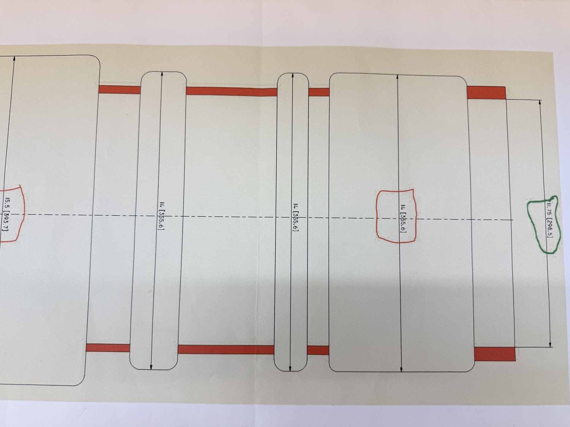 |
January 2026 The drawing shows that the valve cylinder has a number of recesses and these have a internal radius at the ends. Tony now needs to create this in the core box. |
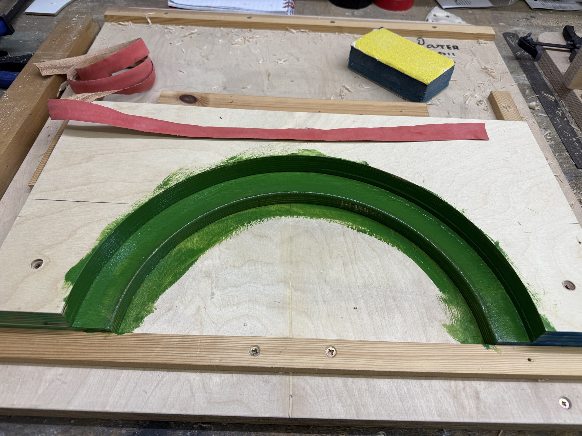 |
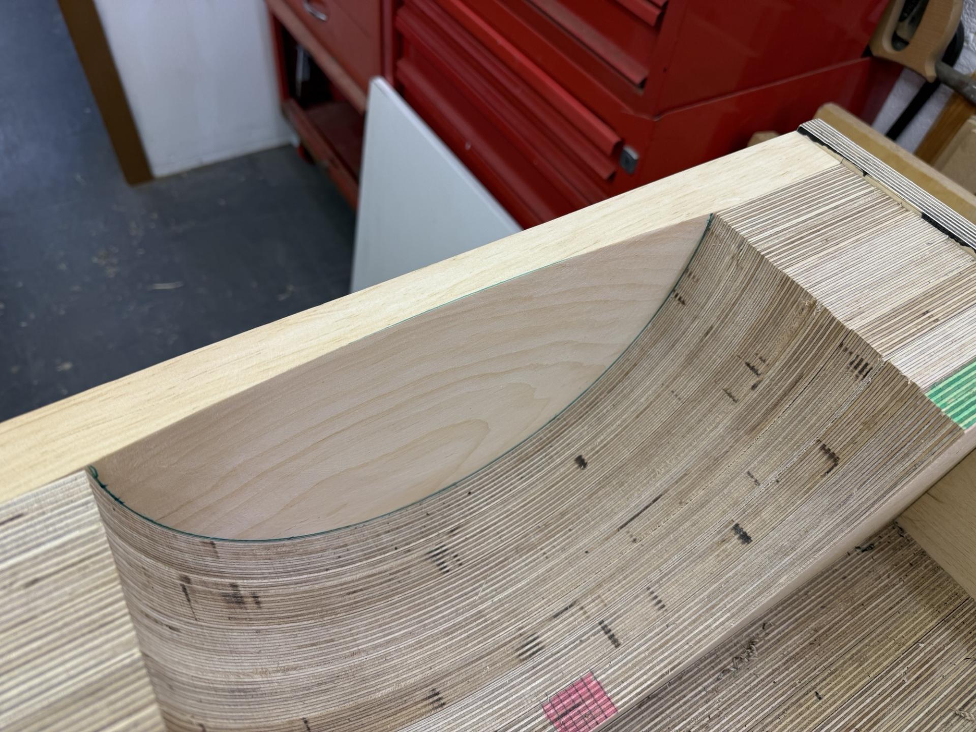
For a trial run, Tony has mocked up a section. He will be using the light gauge red leather strip to form the curve with a special glue. He has painted the area green to provide a contrasting background. |
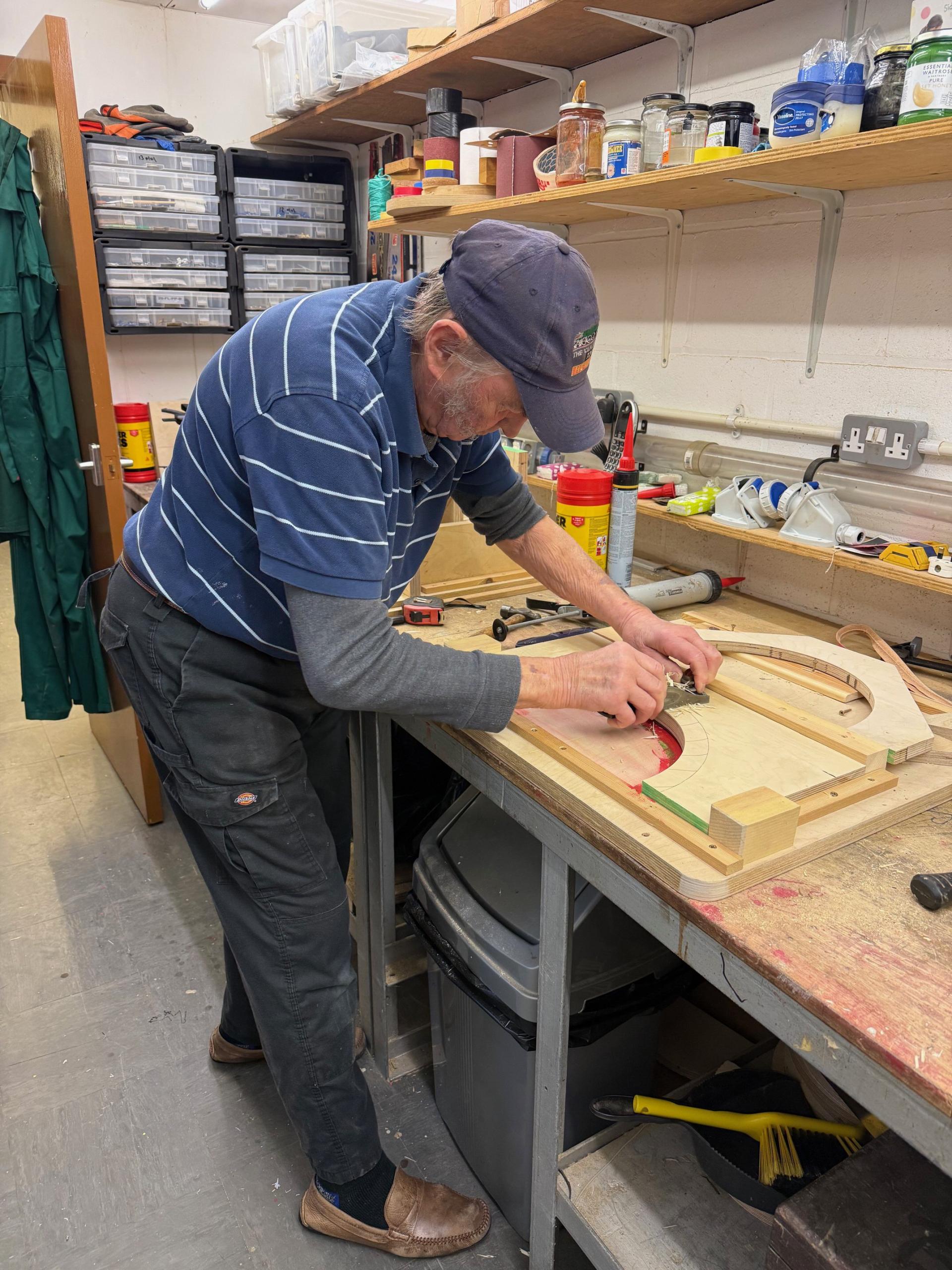 |
Tony now has to work through all of the sections in the core box adding pattern makers "draw" to the vertical faces. A slight taper will help when removing the sand mould from the core box. |
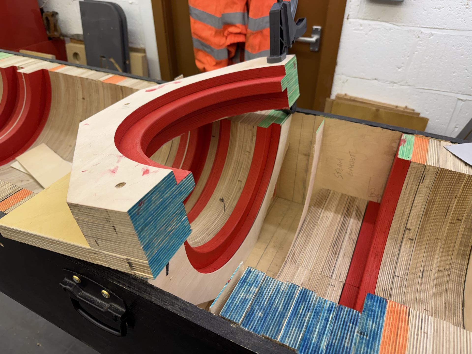 |
Tony has painted red the areas where he needs to apply the leather strips to make the rounded corners. |
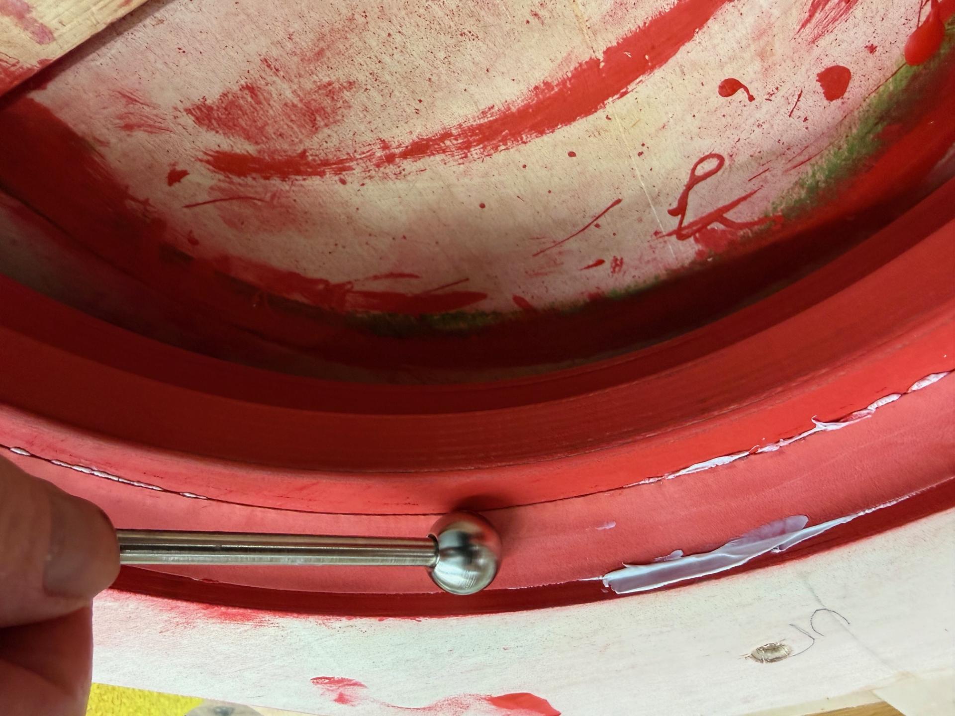 |
This is how Tony is gluing the leather strip in place. This will then allow the radiused ends of the galleries to be formed in the sand core. |
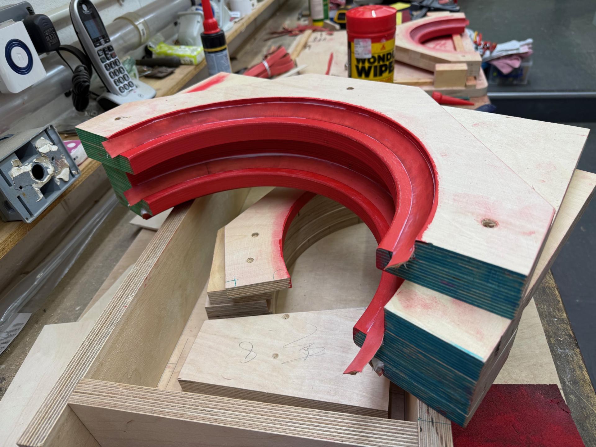 |
A couple of completed sections with the ends to be trimmed off once the glue has set. |
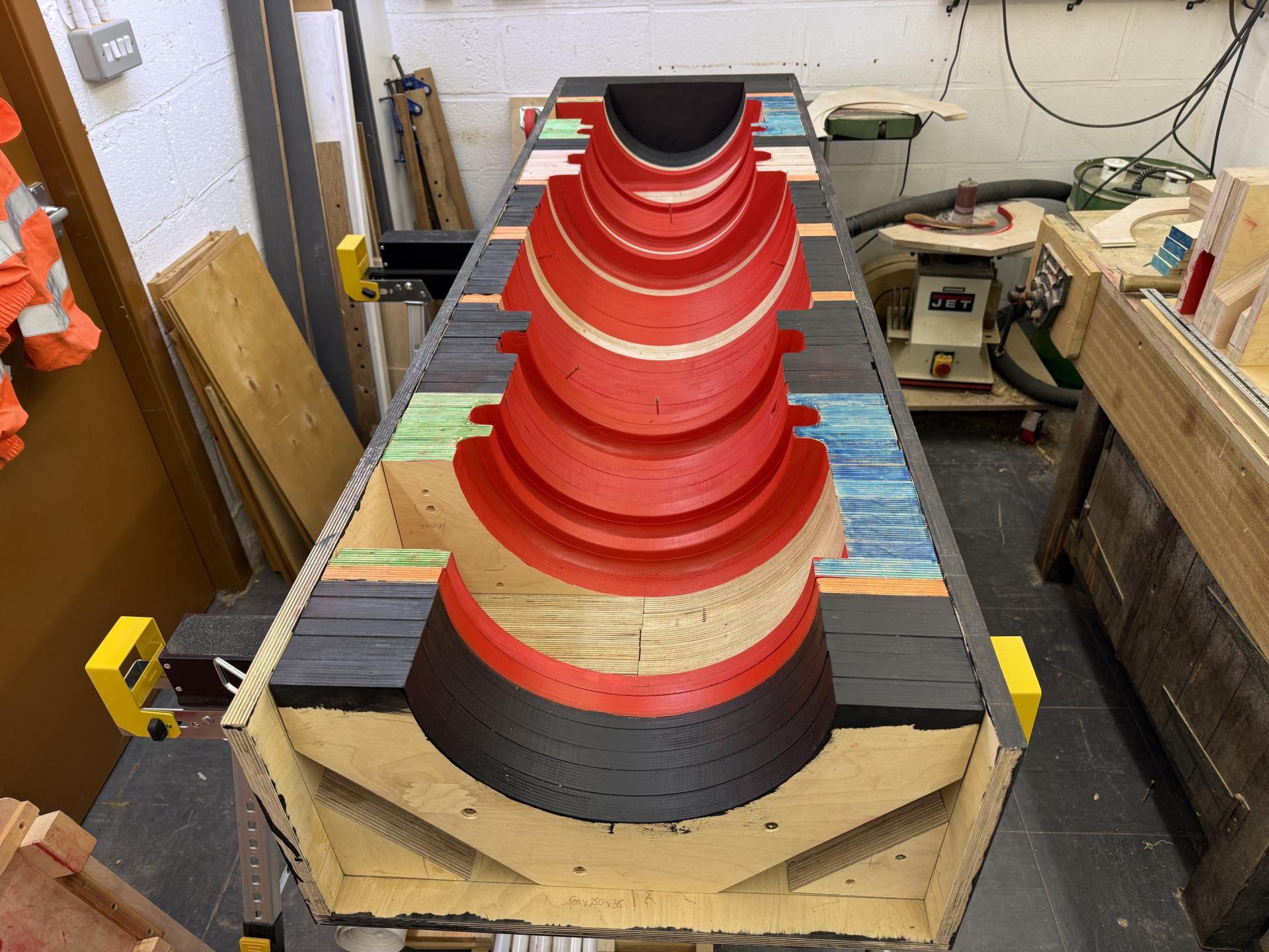 |
Tony is mow working along all of the valve cylinder core box sections screwing them together and painting them |
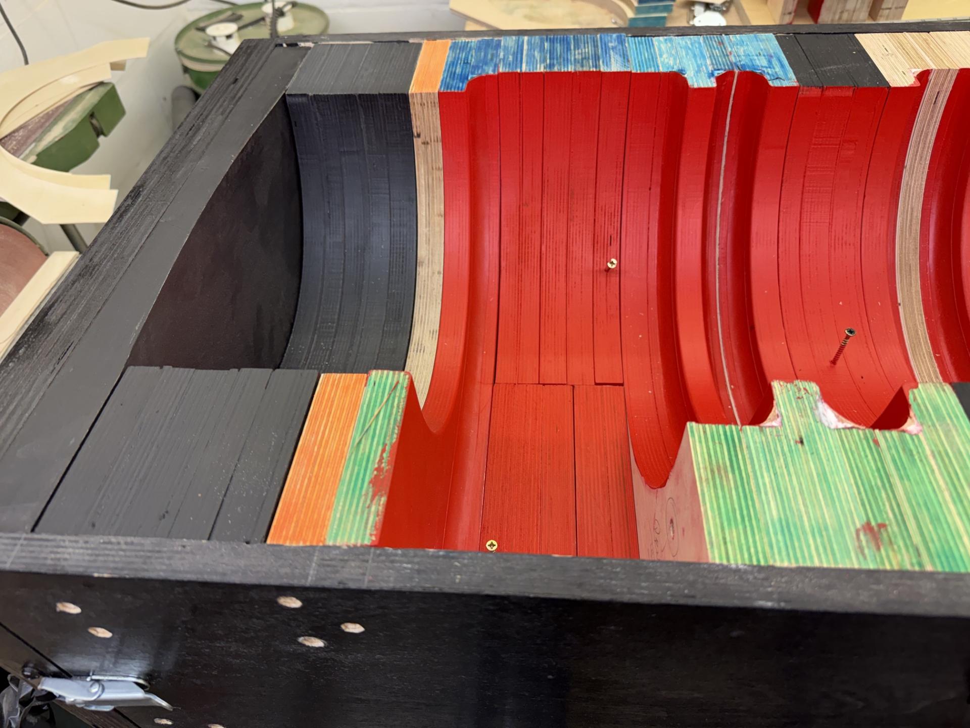 |
The black section is the "print" extension of the core that will fit into the print recess in the sand mould made by the main pattern. The blue section is a removeable piece. The core box will make one half of the code. When the other half is made, the blue section will be removed and replaced by a similar section making the other hand. |
|
First | |
Previous | |
Back to Index | ||||
| 240 records found. Page 24 of 24 displayed. | |||||||||