Help us build the Front Bogie
| If you would like to make a donation to the bogie appeal, please click the button |
The front bogie of a steam locomotive is a 4 wheel, unbraked truck. It's job is to carry the weight of the front of the locomotive and control the entry into and out of curves. The building of the bogie is the next stage of building Hengist after initial frame assembly is complete. In order to build the bogie, we will need to procure the components.
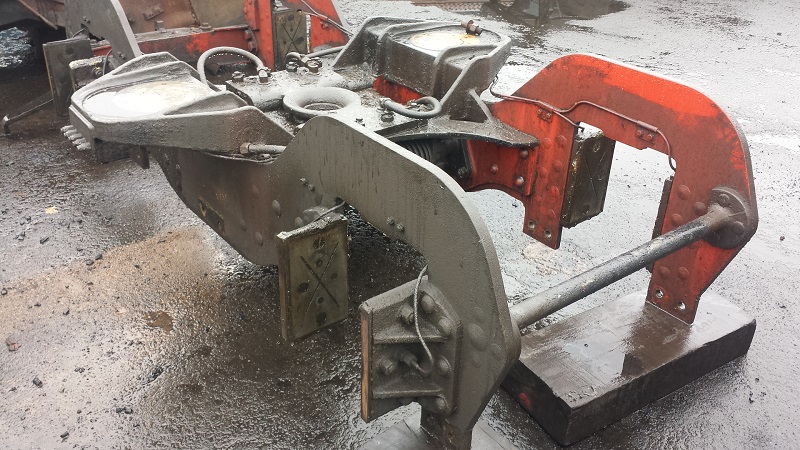
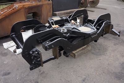
The photo above shows the front bogie from 71000 Duke of Gloucester in a partially stripped condition. The central slide for the bogie pivot can be seen with its flexible oil lubrication pipes. The metal pipes are grease feeds from the grease nipples on the left side of the bogie stretcher. The axlebox guides and their manganese steel liners can be seen. The side check gear spring is just visible.
The manufacture of the bogie will be broken into 3 phases :
- Phase 1 - Manufacture of the bogie frame and side check gear.
- Phase 2 - Manufacture of the axles, axle cannon boxes and fitting of tyres to wheels. Assembly of the wheels and axles.
- Phase 3 - Manufacture of the springs and spring cradle. Installation of lubrication system.
Current Status - Updated 11 May 2023
All of the components for phase 1 are ready for assembly. Assembly is in progress, currently with the fitting of the frames to the central bogie stretcher.
Phase 1
- All components are ready for assembly.
- Final checks of frame plates to ensure that all sharp edges have been removed are complete.
- The frame plates are being fitted to the central stretcher.
- The frame alignment has been checked.
- The first set of bolts with hexagonal head have been fitted
- A number of the frame plate to stretcher bolts have large countersunk heads - to avoid fouling the spring cradle. The countersinks on the frame plates will be formed on a machine. An order has been placed with CTL Seal for this work.
- The axlebox guides have completed initial maching and are ready for assembly. Final machining is waiting for machine time.
- An order has been placed with CTL Seal for the axlebox liners. These steel liners have manganese steel liners welded to them. The final job will be to set up teh correct clearance between the axlebox liners and the cannon box liners (which are also manganese steel).
- Lubrication components have been manufactured by a member.
- An assembly procedure has been written.
The frame assembly is waiting to be transferred to the machine shop..
Phase 2
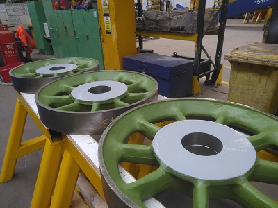
The bogie wheelsets are assembled with some minor components to be fitted.
Progress to Date
- All components manufactured. SSLC had to create drawings for the internal axlebox components as no drawings were available.
- The cannon axleboxes were assembled at South Devon Railway Engineering.
- Wheels were pressed on the axles at SDRE.
- Wheels were turned to the finished diameter at SDRE.
- Tyres were fitted to the wheel and the tryes turned to the correct profile at SDRE.
The wheelsets are now in Sheffield waiting assembly to the bogie frame assembly
Phase 3
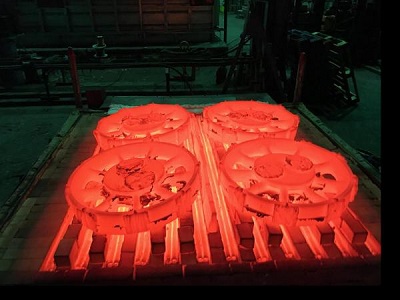
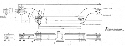
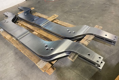
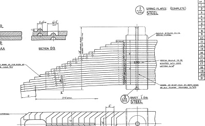
Phase 3 deals with the suspension components which are the leaf springs and the spring cradle. The cradle presented a challenge as it would have been manufactured by pressing over formers. The cost of creating formers would be too high for a one-off project so alternative methods were developed. The cradles were machined from solid by Tyler Bros in 3 stages. First, machining from a solid block of steel to a rough shape. Second - stress relieving by heat treatment. Third - final machining to shape.
- The spring cradle plates have been manufactured and have been assembled by Heritage Rail Traction in Manchester.
- An order has been placed for the suspension springs.
- Some minor components need to be procured.
- We are still trying to find a suppier for the rectangular cross section side control springs. These can be fitted at any time.
Phase 1 - The Bogie Frame
| If you would like to make a donation to the bogie appeal, please click the button |
For phase 1 of the bogie construction we are aiming to complete the bogie frame and its associated components. Assembly is in progress.
Click on the images below for a larger pictures.
| Bogie Stretcher Casting | |
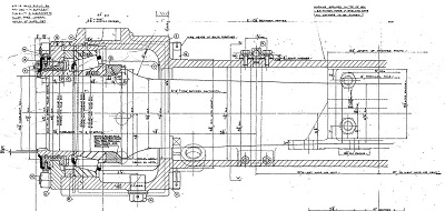
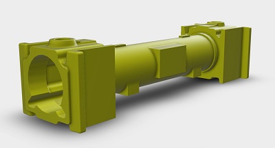
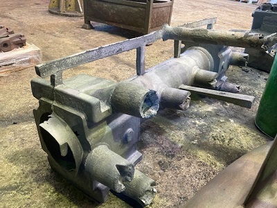
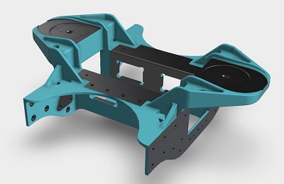
| The bogie stretcher casting is the central 'skeleton' within the bogie upon which everything else is built. The 2 round areas are where the bogie bolsters engage; these carry the weight of the front of the loco. The central area is where the centre slide is located. The part has been cast in a foundry and then will be taken to a machining shop for machining - these are the grey areas on the drawing Status - Ready for Assembly. |
 |
| 17 February 2020 - The stretcher has been received from the foundry and is shown here going through dimensional checking at CTL Seal. The stretcher is upside down and is being checked with the use of a Faro Arm. This creates a 3D model of the stretcher which can be checked against the drawing. | 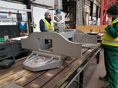 |
| 28 April 2020 - The casting is now undergoing machining at CTL Seal. | 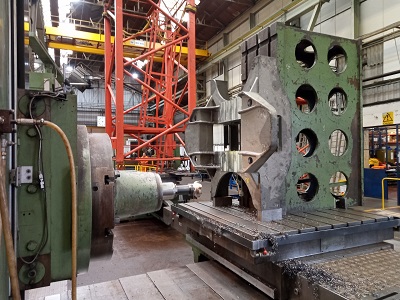 |
| 17 August 2020 - Machining almost complete. Inspection picked up a couple of areas that require rectification. rectification of final anomaly in progress. | 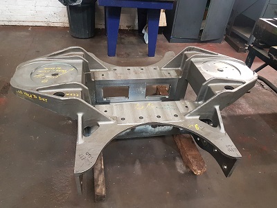 |
| 18 October 2021 - Machining complete and trial fit in progress. The photo shows the Automatic Warning System Receiver Stay and Lifeguards in place. The plan now is to ensure components fit. We will then assemble the bogie frame with temporary bolts and then check that everything is aligned correctly. We will then follow the same process as for the frames, i.e. drill and ream all assembly holes to final size and the install the fitted bolts. | 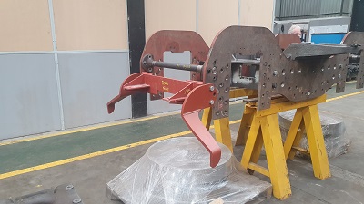 |
| Bogie Centre Slide | |
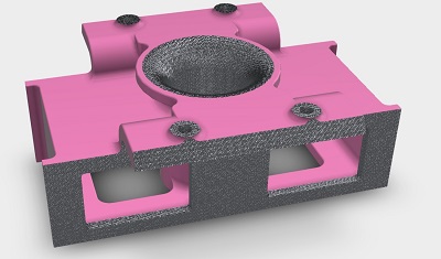
| A pivot pin fastened to the underside of the locomotive frames engages with the central hole of the centre slide. The centre slide has the ability to move left and right on the stretcher casting but is restrained by centering springs. This ensures that when a locomotive enters a curve, the forces on the bogie wheel flanges are kept within limits. It also ensures that the loco is recentred after leaving a curve. The slide is a casting which will require machining after casting. Status - Machining complete. Central bush will need fitting but this is not a priority. |
 |
| The centre slide has been cast by South Lincs foundry. | 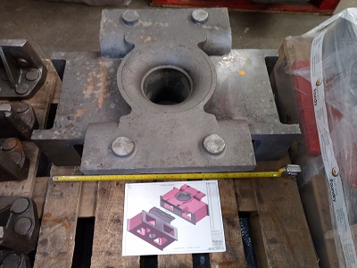 |
| August 2020 - Stage 1 machining complete - waiting to go on a CNC machine. | 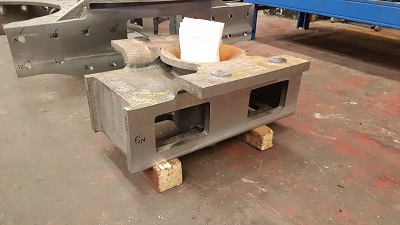 |
| February 2021 - Machining in Progress. | 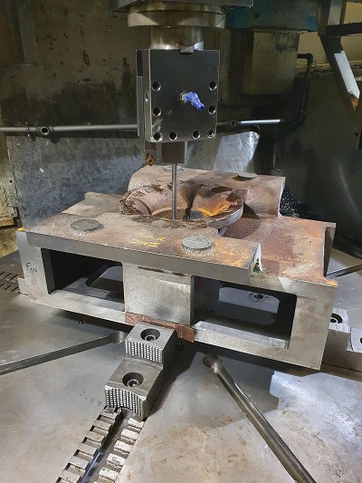 |
| April 2021 - Machining Complete. Geoff and Alan try out the cast iron pivot bush for fit. This will need to be shrunk in liquid nitrogen before fitting. | 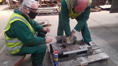 |
| A bush is required in the centre slide which the centre pivot engages in - Ready for Assembly 2 wearing plates are required for the central slide to operate on - Ready for Assembly 4 bolts are required for the plates - Ready for Assembly |
|
| The 2 V Strips that hold down the centre slide are on the left. These restrain the centre slide vertically but allow it to move sideways. On the right is the pivot pin bush that will need to be pressed into the centre slide. It is secured by 2 substantial set screws. | 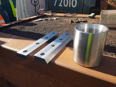 |
| 2 wear plates are bolted to the bogie stretcher and the centre slide sits on these wear plates. The V strips are bolted to the top of the plates | 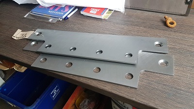 |
| Spring Pads | |
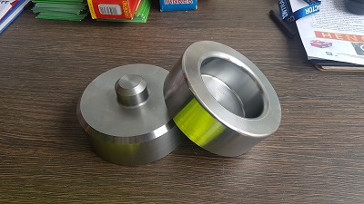
| These are the spring pads that sit between the bogie stretcher and the central buckle on the leaf springs. The "pip" on the left hand pad is welded into the arm on the bogie frame stretcher. Status - In stock, ready for assembly |
 |
| Bogie Side Check gear | |
| On the front and back of the bogie, there is the side check gear. This controls the movement of the bogie centre slide. For a full explanation of what is involved here, take a look at the bogie pages in the build section. The coil springs are rectangular section which are proving difficult to source. Currently we have one potential supplier. There is the option of using a round section coil spring but this will need in and outer springs to provide the same spring properties. This option will probably require a validation exercise. |
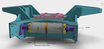 |
| To complete the side check gear, we need : 2 off Spindles - In Stock, Ready for Assembly 2 off Distance Pieces - the orange item. The inner ends of the spring rest here - requires resolution on spring type 4 off Spring Guides - the fawn item. The outer ends of the springs rest here - requires resolution on spring type 4 off Stops - the fawn item. These locate spring guide in the yellow beam arms - requires resolution on spring type At the moment the design is not finalised in this area so we are not currently seeking sponsors for these items. The issue is that the springs are rectangular section. We are having difficulties in finding a supplier who can still manufacture this size of rectangular section spring. |
|
| Beams - Centre Slide to Side Check Gear | |
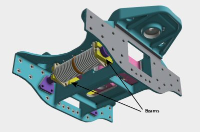
| The Centre Slide must be restrained in movement by the Side Check Gear and the springs. 2 substantial beams connect the 2 components. The beams (yellow in the drawing) are fitted in slots in the centre slide. As the centre slide tries to move, it moves the beam which compresses 2 of the springs (one fore, one aft) Status - In Stock, Ready for Assembly |
 |
| 28 April 2020 - One of the side beams on the machining station at CTL Seal. the outstanding job is to machine the radiused surface on the top of the beam. | 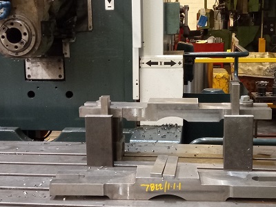 |
| July 2020 - Machining Complete. Ready for Assembly | 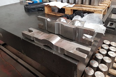 |
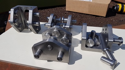
| 4 brackets are required to locate the side control spring spindles. The brackets are shown in purple above. These brackets have been manufactured by CTL Seal. | 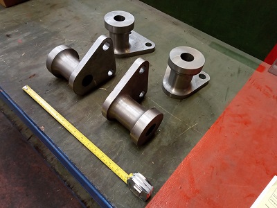 |
| Bogie Pivot | |
| The pivot is bolted to the underside of the main frames into the Frame Stretcher for Bogie Pivot. This pivot then engages with the centre slide on the bogie. Status - In Stock, Ready for Assembly |
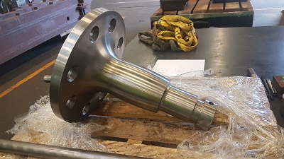 |
| Pivot Collar and Locking Ring | |
| Once the pivot on the locomotive frames has been engaged with the centre slide of the bogie, a 2 halves of a pivot collar are fitted and then a locking ring secures the pivot collar. These are fitted underneath the centre slide to prevent the bogie from disengaging with the pivot. There are 2 components Pivot Collar - In Stock, Ready for Assembly Locking Ring - In Stock, Ready for Assembly |
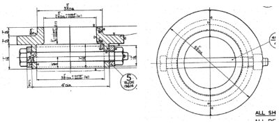 |
| Here are the components part way through manufacture. Top is the locking ring. Middle are the 2 halves of the pivot collar that engage in a slot on the bogie pivot. Bottom is the securing bolt | 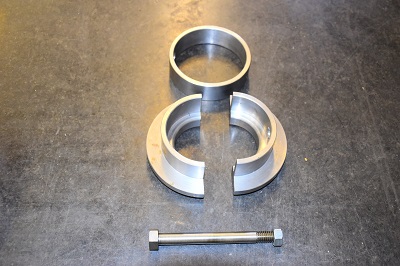 |
| 30 September 2019 - This is the complete assembly fitted to the bogie pivot pin. The 2 halves of the pivot collar fit in a groove in the pivot pin. The locking ring fits over the pivot collar to hold the 2 halves in place. The assembly is secured by a nut and bolt. | 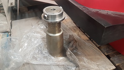 |
| Bogie Frames | |
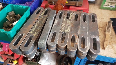
| 2 bogie frames are bolted to each side of the central stretcher. These will require final machining and drilling for the various bolt holes and fixing holes Status - In Stock, Ready for Assembly |
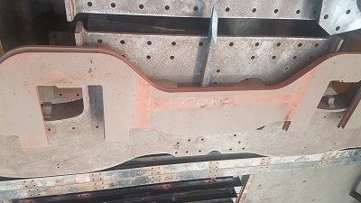 |
| 17 February 2020. The frame plates have almost completed machining. Some light chamfering of holes is required to complete the job. | 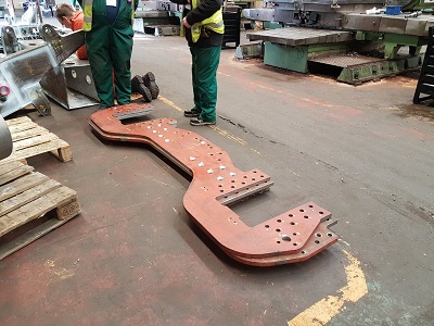 |
| 23 February 2020. Frame plates complete and read for assembly. The top frame has the front to the right, the bottom plate has the front to the left. The difference between the 2 ends is due to the fitting of the lifeguards and the Automatic Warning System Receiver stay. | 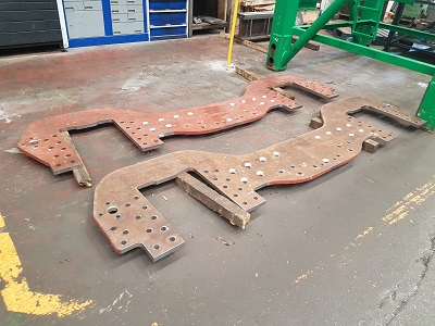 |
| Bogie Frame Stays | |
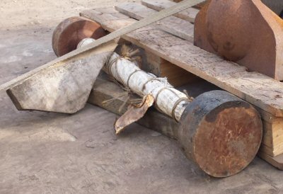
| The front and rear of the frames are braced in position by 2 frame stays, 1 forward, 1 aft. The photo shows the stays prior to machining Status - In stock, ready for assembly. |
 |
| Here are the stays ready for installation. | 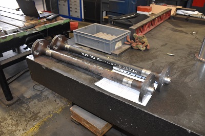 |
| Axlebox Guides | |
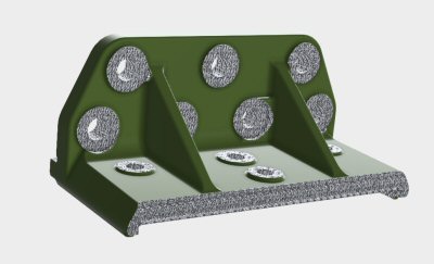
8 axlebox guides are bolted to the bogie frames. These will allow the axleboxes to move vertically within the guides. Manganese Steel liners are bolted to the face of the guides and is the rubbing face for the axleboxes. Manganese steel is very hard wearing. |
 |
|
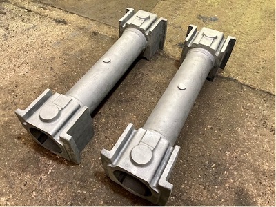
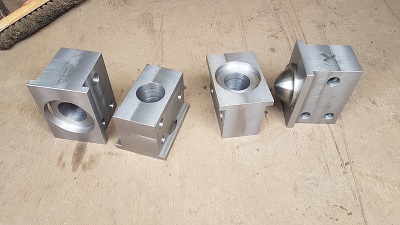
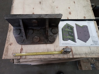
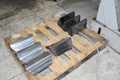
The axle guides have been cast by South Lincs Foundry and are now at CTL Seal. From a casting point of view, the 8 guides are identical. Machining will produce 4 of one type, 2 of the second type and 2 of the third type. The main difference is the recessed bolt holes to make sure that the fastener head does not foul the bogie spring cradle. |
 |
|
July 2020 - First stage machining complete. Second stage machining in progress. |
 |
| Bogie Bolster Cups 2 bogie bolsters fitted on either side of the main frames at the front of the loco transfer the weight to the bogie via these bogie bolster cups. These are free to "float" on the top of brass pads fixed to the bogie stretcher casting |
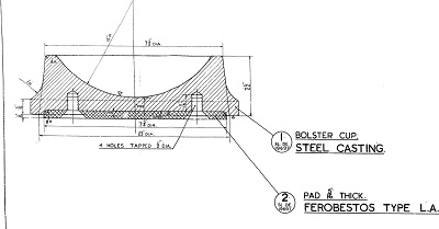 |
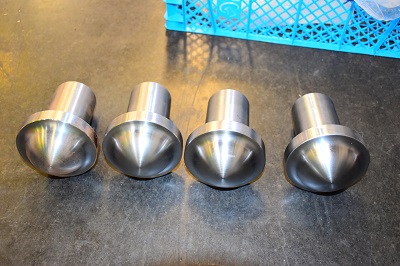
| Here are the completed bogie bolster cups. The right hand one is upside down and and, originally, a Ferobestos pad was fitted in the recess. This will be replaced by a Tufcot pad (in stock) that has similar characteristics to Ferobestos but without the asbestos. The Ferobestos/Tufcot pad provides a degree of damping. | 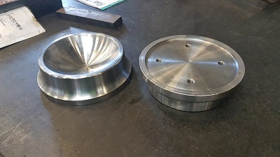 |
|
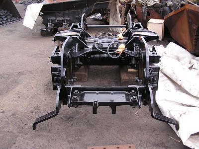
In 1959 to 1960, most of the Clans were fitted with BR Automatic Warning System. You can tell if it has been fitted by the presence of a protection plate behind the screw coupling on the front drawhook. Part of the installation was a new fabricated receiver stay as seen here between the lifeguards on 71000's front bogie (photo courtesy Michael Hughes from the BR Class 8 Steam Locomotive Trust). We will not be procuring the central joggled plate yet. Almost certainly, we will need to mount other signalling detection systems here such a TPWS so we will leave that decision until later. |
 |
| The AWS Stay ready for installation | 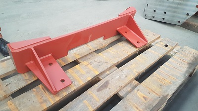 |
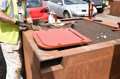
| To complete the AWS story, this is the AWS receiver protection plate. It is fixed to the bottom of the front buffer beam and it's job is to protect the AWS receiver from the drawgear shackle. On old photos, if you see this plate, it's a quick way of telling if a loco was fitted with AWS. We have had the plate in stock for sometime so here Ashley has cleaned it up and given it a fresh coat of primer. |
 |
| The 4 bogie frame keeps have been manufactured and are in stock | 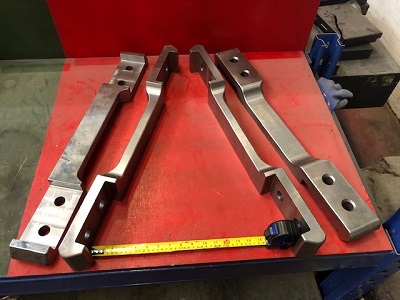 |
Phase 2 - Axles and Wheels
| If you would like to make a donation to the bogie appeal, please click the button |
Phase 2 tackles the wheelsets. The wheelset is a complete assembly comprising of the axle, cannon box with bearings, wheels and tyres. Wheelset assembly is in progress at SDRE. Some minor components for the cannon boxes are still required.
Phase 3 - Suspension
| If you would like to make a donation to the bogie appeal, please click the button |
Phase 3 is the final phase and will involve the manufacture of the spring cradle and procurement of the leaf springs. The final task will be the installation of the bogie lubrication system. Oil for the centre slide and grease for the axle box guide liners.


