Front Bogie
| Back to Index | Next | Last | |||||||
| 109 records found. Page 1 of 11 displayed. | |||||||||
For most of the photos on this page, you can click the image for a larger picture.
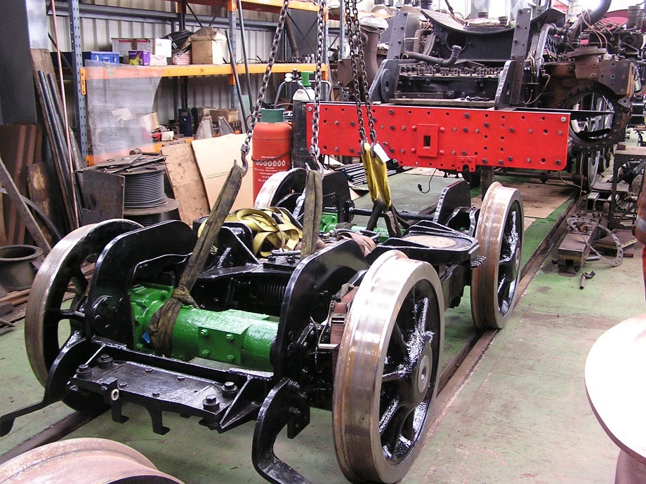
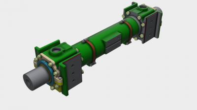
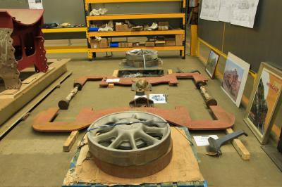
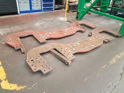
We are grateful to Michael Hughes from the BR Class 8 Steam Locomotive Trust for the reproduction of the above photo which shows the front bogie from 71000 which is similiar to a class 6 bogie.
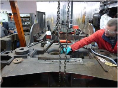
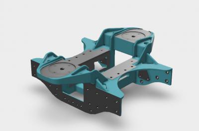
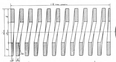
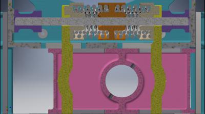
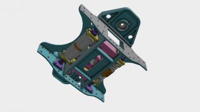
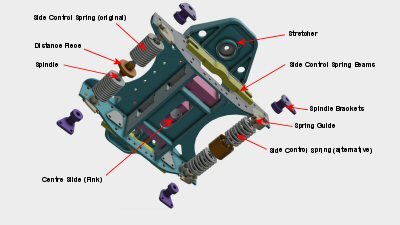
The front bogie in a Pacific class steam locomotive is a four wheel, unpowered truck. Part of it's job is to carry the weight of the front of the locomotive. It's more important job is to allow the locomotive to negotiate curves as the driving wheels are rigidly kept in line by the frames. The front bogie must not only be able to pivot around a central point but it must also be allowed to move sideways relative to the locomotive frames. This sideways movement must be controlled by heavy duty springs and the selection of these springs is critical to the ride of the locomotive. The bogie guides the locomotive into the curve and avoids placing undue stress on the flanges of the bogie wheel.
From his autobiography, Locomotive Panorama, Vol 2 we know that E.S.Cox (the person responsible for the design of the BR standards) was involved with William Stanier (the CME of the LMS railway) in the 1938 Indian Pacific Locomotive Committee. There had been severe hunting and track distortions following the introduction of an XB Pacific locomotive in India. In July 1937, a serious accident at Bhita occurred where 100 lives were lost and rail distortion due to hunting was considered to be the cause of the derailment. A committee of engineers including Stanier and Cox went out to India to attempt to identify the cause.
Cox describes about a trial run "Between Calcutta and Ranaghat oscillation was continuous above 35 mph but as it touched 60mph, it quickly started to build up until the engine was crashing from side to side with rapidly increasing intensity. The driver shut off and braked heavily and normality returned, but behind our blenched faces our minds registered most accurately the antecedents of Bhita"
Cox then goes on to describe the finding of the solution to the problem.
As we got nearer to the home ground of the Railway Board, resident in Delhi in the Winter and Simla in the Summer, emissaries came out to meet us and demonstrate to us the results of their own intensive thinking and research work. We were shown the means of flange force measurements which two of their young engineers, Gelson and Blackwood had developed, and were presented with a wooden case containing over 100 of the records they had taken. Not only this, but we were told that the problem had been solved and that the records proved such to be the case. The solution had consisted of greatly increasing the friction on the horizontal bogie rubbing surfaces, sufficient to damp out all hunting tendency. The Board were prepared to go to town on fitting up all the locomotives accordingly, and only awaited our blessing.
Now one of the members of our Committee came from a background and experience far removed from the British school of thought. Robert Leguille, a son of Alsace, and quite the opposite of the typical Frenchman in his bluff square appearance and more phlegmatic approach, had had to live all his professional life with big 4-6-2's and 4-8-2's working over what was none too good track in those days before World War II. French theorists such as Marie and Blondel, had peered into the fundamentals of exactly the same problem, and had established the relation between moment of inertia of the mass of the locomotive and its side control. More recently Mauzin had. developed test equipment and procedure in verification. Leguille, therefore, knew enough to suspect that there was more in the problem than damping values only, and had been gradually influencing the Committee's thoughts. So it came about that he and I shut ourselves up in our car on the special train we travelled in, and spent eight hours one steaming hot Saturday in a siding outside the East Indian station in Calcutta, examining every inch of every flange force record which had been presented to us. At the end of this travail we had the evidence of the Railway Board's own charts that they had not solved the problem, for these showed that while the increased friction reduced flange forces on straight track, it did nothing to reduce them on curves, and that only a combination of stronger side control springs plus appropriate damping could give the desired result.
Our trip ended with three weeks in Simla, like heaven with its clear cool air after the heat and dust of the plains below, and there we did battle with the Railway Board in long technical sessions. In my bedroom in the Cecil Hotel, its open windows looking at the snowclad backdrop of the Himalayas 50 miles away, and covered with wire netting against the depredations of the monkeys, I drew out with my own fair hand a means of converting the X class bogie to take the stronger springs which were essential, and which the form and dimensions of the original bogie could not accommodate. By introducing at the same time the French-Western-Stanier assembly of opposed action side control springs, all possibility of uncontrolled free side movement was eliminated. This drawing was sent on ahead of us to the Dohad Works of the BB. & C.I. Railway, and when we Visited that centre on the final stage of our return to Bombay, we saw and rode with XC. No. 614 so altered. This seemed to indicate that we were on the right track, and flange force tests carried out soon after we left India indicated a 20% reduction in flange forces at 60 m.p.h. compared with the previous standard, and with no tendency to any build up of oscillations.
There was, of course, also an important track element in the whole problem, in that while the locomotives were insufficiently controlled, they were too sensitive to even quite acceptable track deteriorations, and to ensure that track maintenance standards did not fall lower than a certain level was a necessary concomitant to the measures which the locomotives themselves required. But the important change which was needed lay in the engines and not in the track.
Thus ended something of a railway 'Who-done-it'. Dhawan, Bakhle and Leguille, all of whom can be seen in Plate 27 taken on board the 'Narkunda', returned to England with us, and to me fell the job of writing the mechanical engineering part of the report. Mount subsequently received a knighthood in recognition of his services, and this reward was richly deserved by his perseverance and integrity. The Report led to modifications to existing and future Indian engines which banished this nightmare for good, while at home there was a general review leading in a number of cases to modifications in the lateral controls on L.M.S. engines, and even on some of those on other British railways. The landmine over which we had lived for so many years was at last rendered harmless."
Cox concludes by saying that "only a combination of stronger side control springs plus appropriate damping could give the desired result".
There are similar reports in other books by Cox so we know that the right amount of lateral control is critical in a locomotive bogie.
| Back to Index | Next | Last | |||||||
| 109 records found. Page 1 of 11 displayed. | |||||||||


