Casting - Cores and Prints
For most of the photos on this page, you can click the image for a larger picture.
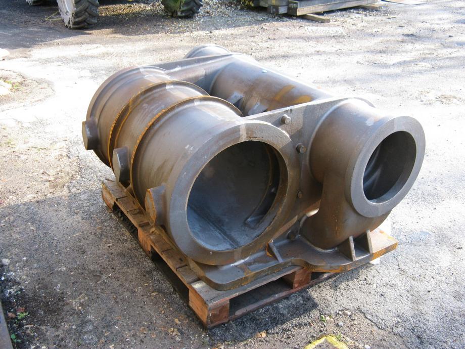
The photo shows a completed cylinder casting that is very similar to the cylinders required for Hengist.
When your web site developer first met Tony, our outside cylinder pattern maker, he was puzzled by references to "cores" and "prints", especially as there were no bits of paper in the vicinity. So Tony is going to explain the place of cores and prints in the making of a cylinder casting. Tony takes over the story.
What are 'Cores'? There are two types of core, both types essentially create the 'holes' or spaces where molten metal is not required during the casting process. To illustrate the formation of one such hole I am going to show the construction of the core required to allow exhaust steam to be compressed in a cylindrical cast of iron to form a blast in a steam locomotives smokebox. This steam blast, when passing up through the smokebox chimney, creates a vacuum which draws the hot products of combustion through the boiler tubes, thus further raising the steam required by the cylinders for the motion of the locomotive.
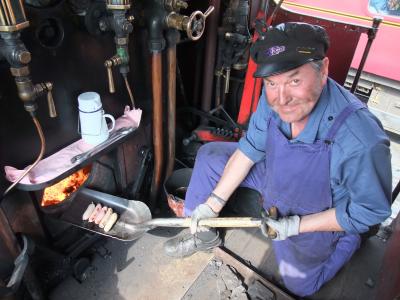 |
Tony has had real time experience of working on the footplate. Here's the best way to have a railway breakfast |
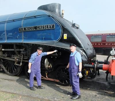 |
Shunting Sir Nigel Gresley at the Bo'ness railway in Scotland |
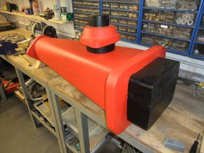 |
On the bench is the pattern for a blast pipe and cap which will be used for the casting in Spheroidal Graphite (SG) iron blastpipes for a number of Hunslet Austerity locomotives. The red part of the pattern represents the iron cast and the black parts are locating sections or 'prints' which form depressions in the moulding sand to hold the Core prints while being part of the pattern are not part of the cast item. |
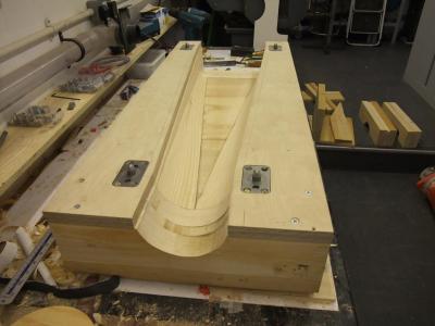 |
From the previous photograph, the black 'print' sections of the outer blast pipe pattern now have to have a core box made to allow the foundry moulder to make the sand core to form the 'hole' through the blast pipe.
To do this, a box is made in which moulding sand is placed and rammed which subsequently hardens. The end product is a sand core. This photo shows the core box being made up of two sections located together with pins in the same manner as in the cylinder pattern build.
This image shows the first half made up and roughed out, the sections for the top section are on the floor.
|
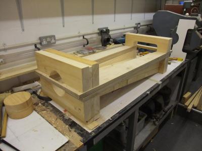 |
The second image shows the second half of the core box being added. The templates can be seen stood up against the lathe. |
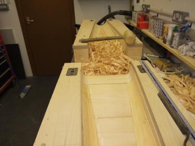 |
The final shaping of the two sections by mallet and gouge. |
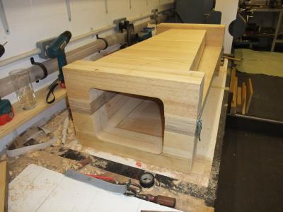 |
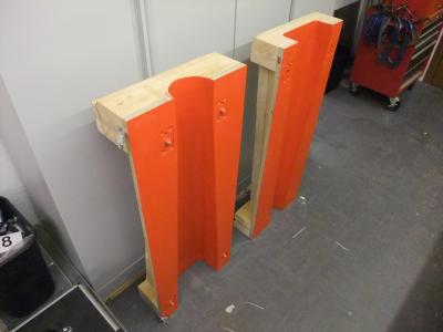
The completed core boxes don't have to look pretty - they need to be functional |
 |
We now move onto the start of the blastpipe cap. This item provides the outlet orifice to produce the blast. |
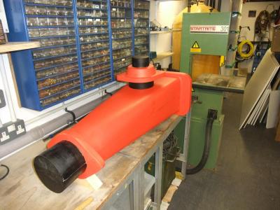 |
The next image shows the blastpipe cap with prints. The core will be the internal section (the hole) designed to produce the blast. |
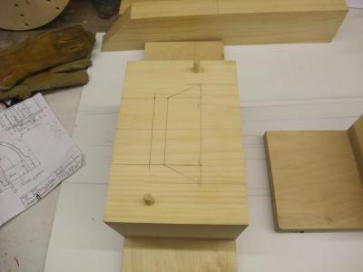 |
This image shows the blast orifice marked out and mounted ready to go on the Wadkin pattern mill. The production of Engineers' Patterns, Coreboxes, etc., by mechanical means was made possible for the first time by the development in 1897 of the Wadkin "Mechanical Woodworker". Whereas the cylinder pattern can be produced on a woodworkers lathe, the production of the core pattern is more challenging. |


