Here are the diary entries for this month. You can use the forward and backward links to see the next or previous months. Most photos taken before 2018 are small size. From 2018 onwards, most photos you see below will have a link to a full size image by clicking on the photo.
| 3D CAD Model Updated with Cylinders |
| 06/04/2020 |
| |
 |
| |
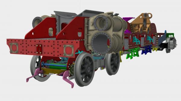
Keith has updated the 3D model of Hengist with the outside cylinders. He has been working with Tony, our cylinder pattern maker, to produce the "core" drawings which will be required to create the airspaces in the cylinder casting. |
| |
|
| Cylinder Pattern Core Production gets underway |
| 06/04/2020 |
| |
 |
| |
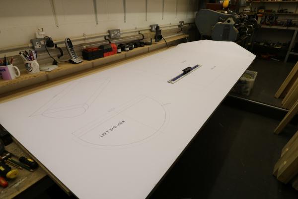
Tony, our cylinder pattern maker, is pressing ahead with the "cores" for the outside cylinders. As the cylinder casting contains a number of airspaces - one being the cylinder for the piston to move in - he needs to create a pattern for these. Here Keith has produced a produced a full size drawing for Tony. On the top left, you can see projections on each end of the core pattern - the "prints" - these will fit into the main sand mould and suport the core mould. |
| |
|
| Valve Cylinder Pattern Progress |
| 12/04/2020 |
| |
 |
| |
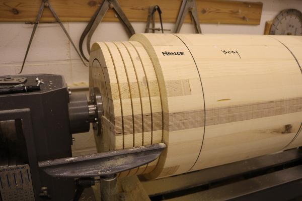
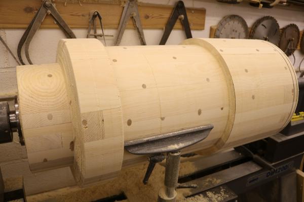
Tony has been finishing the last section of the main valve cylinder pattern. Having turned the blank to prallel, he can now start turning down to the final dimensions. He starts by turning down with roughing cuts to get the blank down to quarter inch oversize,. He's made a series of slots in the end with a parting tool, with the required depth marked by sticky tape. He can happily cut down to the depths without having to constantly check with calipers. |
| |
|
| Intermediate Rubbing Block |
| 13/04/2020 |
| |
 |
| |
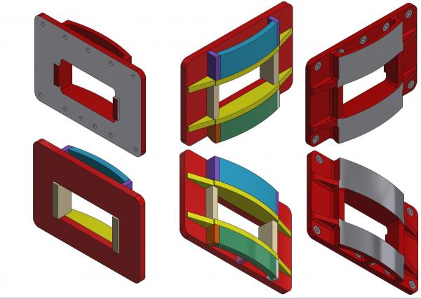
At the rear of the locomotive frames is the hind beam and the various components that allow the locomotive to be coupled to it's tender. 2 spring buffers on the tender push on 2 rubbing plates fitted to the hind beam - these rubbing plates are in stock. They will need to be fitted with manganese steel liners. Between the rubbing plates is the intermediate rubbing block (shown above) with the engine/tender drawbar going through the slot in the centre. It also has manganese steel liners on the curved face. On the British Railways drawings, this component was a casting. We believe that we can manufacture the component as a fabrication using modern techniques. Keith has produced this 3D model and we are currently in talks with CTL Seal as to the best method of manufacture |
| |
|
| Tender Door Hinges |
| 13/04/2020 |
| |
 |
| |
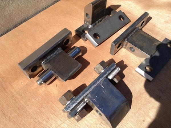
Although Covid-19 restrictions mean that we are having to work from home, we can continue to work on the project. There are 2 hinge brackets that are riveted to each of the 2 tender wing plates that are in turn welded to the front of the sides of the BR1G Tender that we are building for Hengist. The 2 bushes on each bracket are then welded to the outside of the curved cab door rear extension plates. These curved doors are so designed to allow for the fore and aft oscillation of the engine and tender yet remain flexible but securely closed when the locomotive is is running. Yet another example of the myriad of small and minor parts that go to make up the engine and tender. The image shows a completed set of fabricated steel fixing bracket, hinge with pin and bushes assembly; all ready for paint primer. .
|
| |
|
| 3D modelling of Hind Beam |
| 20/04/2020 |
| |
 |
| |
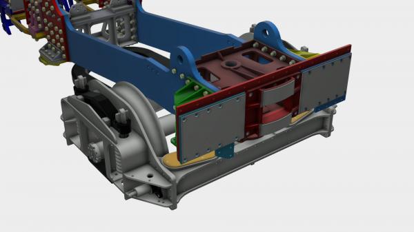
Keith has updated our 3D model with details for the hind beam (red). The hind beam is fittted to the rear of the frame extensions (bue). The outside corners are stengthened by the massive gusset fabrications (green and yellow). On the rear face of the hind beam, in the centre, is the intermediate rubbing block. The engine/tender drawbar goes through the slot in the centre. Manganese steel liners (grey) are fitted to the curved top and bottom faces. Outside of the rubbling block are 2 rubbing plates (dark blue) with manganese steel liner plates on the surface. These take the pressure from 2 "dumb" buffers fitted to the tender. These helped reduce the fore/aft oscillations induced by the loco on the train when working hard and were a modification as a result of service experience with the Brittanias. When the Brittanias were first used on the Great Eastern line (without the mod) you didn't want to take the soup when the restaurant car was behind the loco. It wasn't likely to stay in the soup dish for long! (Bill Harvey's 60 years in Steam) |
| |
|
| Valve Cylinder Pattern Progress |
| 20/04/2020 |
| |
 |
| |
Work on the Valve cylinder pattern continues |
| |
|
| Tender Doors |
| 20/04/2020 |
| |
 |
| |
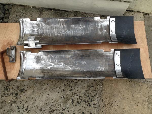
Work continues on the tender doors. The tender door assembly on later tenders consists of 3 plates hinged together. 2 of the plates are flat and the third is curved - as shown in the image. The whole assembly can be folded up and stored against the tender front. Mike has the doors almost ready for assembly. Hinge bushes need to be welded into the slots at the top of the image and the special hinge needs to be fixed in position shown |
| |
|
| Bogie Stretcher Machining |
| 27/04/2020 |
| |
 |
| |
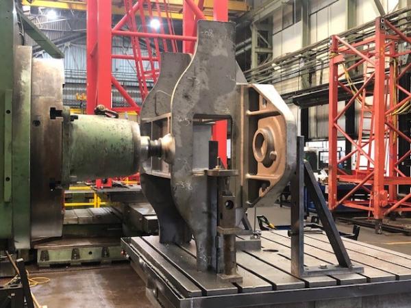
Machining of the central bogie stretcher casting has now started at CTL Seal In Sheffield |
| |
|
| Bogie Brackets |
| 27/04/2020 |
| |
 |
| |
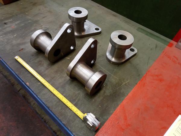
4 new brackets received into stock today. These are bolted to the inside of the bogie frames. They locate 2 spindles that run through the centre of the side control springs. You can see where they fit by following this link and looking for images 7 and 8. |
| |
|
| 3D Model - Dragbox Area Complete |
| 28/04/2020 |
| |
 |
| |
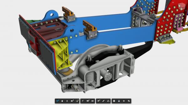
Keith has finished off the components in the dragbox area on our 3D model. The pony truck bolster is bolted to the bottom of the yellow gusset with it's dome facing downwards. It is engaged in the bolster cup which is free to "float" on the oval pad as the rear of the pony truck frame moves. You can also see the rear firebox supports which are bolted to the blue frame extensions. The orange bracket is free to move in a fore and aft direction allowing the boiler to expand as it heats up. |
| |
|
| Bogie Stretcher Machining (2) |
| 28/04/2020 |
| |
 |
| |
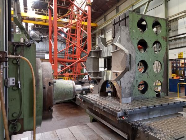
Another view of the bogie stretcher on the machine. You can see that they are woking on the area where the centre slide is located. |
| |
|


